HF Amplifier 1KW Military
P/N 28000-1
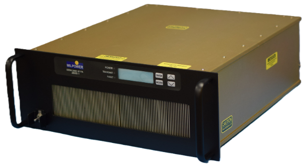
This 19" rack-mounted HF 1KW power amplifier is suited for fixed, transportable, and shipboard applications. This amplifier has exceptional reliability and superior performance with 100/500W +/- 1 dB PEP and average over the 1.6 to 30 MHz frequency range. In addition to the normal modes of operation, it is compatible with high-speed data applications such as LINK-11. The modular architecture of this HF amplifier allows graceful degradation in the event of a malfunction. Control and monitoring are via a serial data interface. The control functions include power output, frequency, keying, and Built-In-test (BIT). The BIT isolates the malfunction of a module level. A separate rack-mounted power supply is provided.
Customers:

Technical Specifications
Frequency Range:
1.6 – 30 MHz
RF Input Power Level:
Requires 2 Watts minimum, 10 Watts Maximum for full power output under all operating conditions.
RF Output Power Levels:
100/500 Watts +/- 1 dB PEP and average over frequency range and temperature. Full power output is the result of combining the output of four lower power amplifier modules. Unit operates at reduced power level if power amplifier module failure(s) occur.
ALC:
All power control is done internally.
Two Tone Intermodulation Distortion (IMD):
Less than 30 dB below either of two equal amplitude signals (36 dB below PEP) separated in frequency by 100 Hz or more driving the power amplifier to full rated power output into 50 ohm load.
Single Tone Harmonics:
Greater than 63 dBc
Spurious:
-60 dBc or better within 5% of operating frequency. –80 dBc or better beyond 5% or operating frequency. (Assumes input signal is at least 10 dB better.)
RF Noise:
At least -140 dBc/Hz at 1 kWatt single tone output. (Assumes input signal is at least 10 dB better).
DC Input:
48 VDC nominal. The DC input is reverse polarity protected and the system is protected from over current.
Input Power Consumption:
3000W nominal
Input Impedance:
50 ohms nominal. 1.5:1 VSWR maximum.
Load Impedance:
50 ohms nominal. Rated power output into 2:1 VSWR. Stable for any load. Reduced power output above 2:1 VSWR. Fully protected from all output VSWR including open and short circuits. Output power drops off gradually at increased VSWR.
Duty Cycle:
Continuous full power output at 55 C. Output power drops off gradually at elevated temperatures.
Protection:
Fully protected from over temperature, over/under DC input voltage, over current, any load/output VSWR and input power levels up to 20 Watts.
Control:
Includes hardware to communicate with external system controller. Receives frequency, R/T, Fhop, bypass, power level and other required control signals. Sends Forward Power, Reflected Power, Faults, BIT and other required info. Interface: serial.
Frequency Change Time:
20 milliseconds maximum between any two frequencies after receiving frequency change command.
T/R Switch:
T/R switching is handled in the amplifier so a single connection is used for the antenna and the receive path goes through the unit.
Bypass Path:
There is a bypass position that is selected through the serial control interface.
Off Path:
With the unit power off there is a single transmit/receive path with minimum attenuation.
Key Control Time:
RF Power is within +/- 1 dB of steady state level in less than 10 milliseconds after receiving key command. (It is recognized this is dependent upon the exciter input amplitude stability following system keying.) RF Power is reduced by more than 50 dB within 5 milliseconds after receiving key off command.
Built In Test:
Built in test is incorporated as a feature to assist in maintenance. Whenever a fault occurs, the front panel FAULT light lights and the fault is reported to the radio through the serial communications interface. Faults include over-temperature, over/under voltage, over current, high VSWR, faulty fan(s) and faulty power amplifier module(s).
Construction:
The unit is modular for ease of maintenance. The unit features a functional set of modules easily accessible for replacement using standard tools. The unit is mounted in a 19-inch rack. Provisions are to be made for mounting slides.
Size:
10.5 H x 22.0 D x 19.0 W, max.
Weight:
80 Lbs.
Cooling:
Forced air internal fans with speed control. Design minimizes exposure of internal components to dirt and dust intake from cooling system. Cooling system minimizes air output from front. Fans are monitored for proper operation. Improper operation should be reported as a fault. Filters are used that can be removed from the front panel for cleaning or replacement.
Acoustic Noise:
55 dBa maximum. Cooling system noise to be kept to a minimum. Fan speed to be automatically reduced consistent with cooling requirements.
Switches:
Power ON/OFF.
Front Panel Indicators:
Power On (green) and Fault (red) lights. An analog representation of RF output is provided.
Connectors:
Separate connectors for DC input 2 X (MIL-C-5015), control/ALC (DB9), RF input (BNC), RF output (Type N). All connections on rear panel. 6 pin Auxiliary connector.
Color/Markings:
TBD.
Operating Temperature Range:
-20 to 55 C at sea level.
Storage Temperature Range:
-40 to +85C.
Altitude:
Operating to 10,000 feet. Storage to 15,000 feet.
Humidity:
0 – 95% relative humidity, non-condensing
